Microcontroller Units (MCUs) [WIP]
This section will cover what you need to know in terms of your keyboard’s brain: the MCU.
Integrated Circuits (ICs)
Great resource to read: Integrated Circuits - Sparkfun
Integrated Circuits are the black chips you see on PCBs. They are the brains of most PCBs.
They have many small internal components that work together to perform certain functions. ICs take inputs and give outputs. ICs can range in complexity, from simple logic gates (e.g. AND/OR gates) to desktop CPUs.
Image of two different types of ICs:

MCUs
The microcontroller is the brain of a keyboard PCB. MCUs are a subcategory of integrated circuits that can range in size, complexity and capability.
I highly recommmend watching these videos, as I won’t be explaining MCUs too indepth. The following videos should give you a good fundamental understanding of MCUs: This video gives you a good idea of what a MCU consists of and how it functions. This other video has useful information, however, the MSP430 section is irrelevant.
For keyboards PCBs, 32-64 pin MCUs (e.g. ATMega32u4, STM32Fxxx, RP2040) are generally used for their small size, relative affordability & availability, low power consumption and firmware support.
Before you move on, it’s a good idea you at least recognise and/or understand the following terms/concepts:
- Integrated Circuit (IC)
- Microcontroller (MCU)
- RAM
- ROM/Flash storage
- GPIO (General Purpose Input Output)
- Clock/frequency
IC Packages
ICs come in a wide variety of packages with varying sizes and usecases. “Packages” are used to divide ICs into categories/formfactors.
Note: Sometimes you might see extra letters added to the package. E.g.”TQFP” or “LQFP” vary slightly, but both fall under the same general “QFP” category. The same applies to other packages. QFN/QFP are just generalisations.
In terms of the common keyboard MCUs, most are either QFN or QFP.
The below image shows some common IC packages

Common keyboard MCUs (brief)
These are some common microcontrollers that keyboards use. I’ll discuss the pros and cons of each MCU in the following list in the Design Considerations section, but here is the list for now:
- AVR family (AVR)
- ATmega16U2 / ATmega32U2
- ATmega16U4 / ATmega32U4 (what I’ll be focusing on for this guide)
- AT90USB64 / AT90USB128
- AT90USB162
- STM family (ARM)
- STM32F072
- STM32F042
- STM32F103
- STM32F303
- STM32F411
- STM32F401
- Raspberry family (ARM)
- RP2040 (new)
MCU Pinouts and Datasheets
Want to know more about reading datasheets? Watch this.
Every MCU will have a piece of documentation called the datasheet. It basically describes what the MCU’s capabilities are, its required components, routing guidelines, size/shape, pinout, etc. It’s a good idea to get familiar with reading datasheets, as they provide lots of useful information.
For example, have a look at the ATMega32u4 datasheet.
A MCU pinout is a term used to refer to any piece of information that explains what each pin on the controller does. It will tell you what components to connect and where. E.g. You can use it to find all the GPIO pins (pins used for switch matrix), which pins to connect D+/D- traces to, which pins to connect your oscillator to, etc.
Note: All components have datasheets and pinouts, not just microcontrollers.
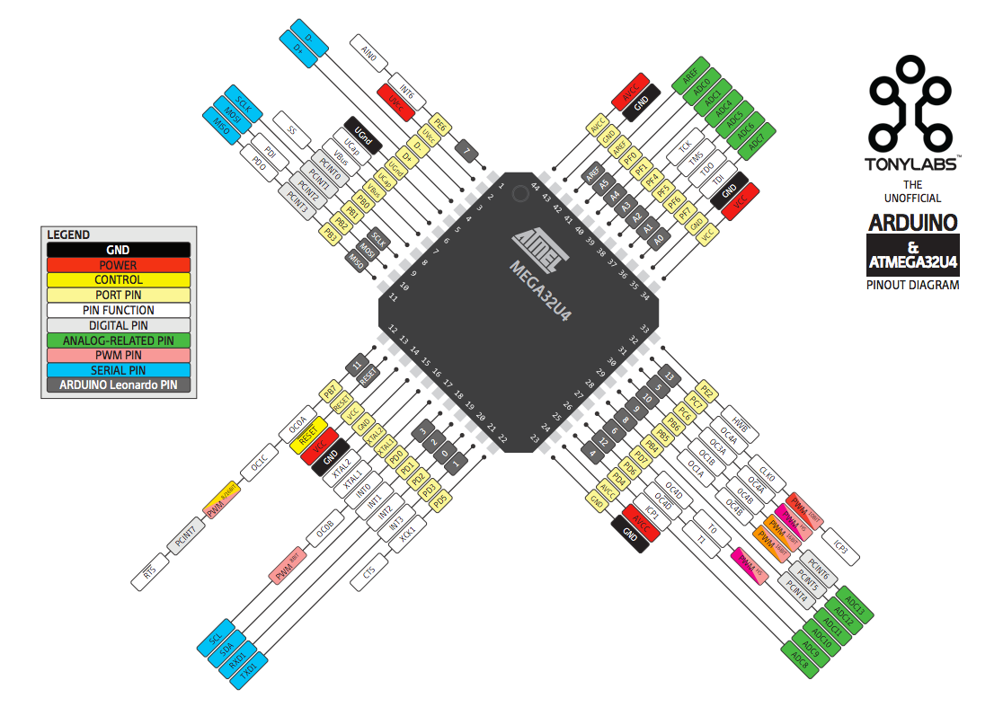
The following diagram is a pinout diagram for the ATMega32u4 (by 14core):
Decoupling Capacitors
Good resource: The basics of decoupling capacitors (I really recommend giving this one a read), What is the Use of a Decoupling Capacitor?
Decoupling capacitors are used to help provide ICs with a steady voltage/supply of power. MCUs, for example, are an IC that require a steady voltage to protect the sensitive circuitry inside. EMI can cause noise throughout the PCB/circuit and lead to an unsteady voltage. By placing decoupling capacitors close to the controller, they can effectively reduce noise by creating a small power loop. Supplementary power is supplied when the voltage drops too low and excess power is absorbed when voltage is too high.
Placement/routing of decoupling capacitors is important. Correct placement and routing allows them to properly fulfil their role/purpose. While the chances are low, controllers may not function correctly if supplied voltage is too unstable. There are many resources online regarding decoupling capacitor placement/routing (one is linked above), but I’ll be going over how you should layout them later on (specifically for the MCU we will be using in this guide).
Placed close to the MCU, one 100nF capacitor for each VCC (power) pin is generally used in combination with a 10uF bulk capacitor (placed closer to the USB connector). This will vary from controller to controller, so the datasheet can give information in regards to exactly what value capacitors to use and where to place them. Examining known working examples of decoupling capacitor placement/tracing is also helpful.
Note: “decoupling capacitor” or is just a name given to certain capacitors with that specific role, they aren’t a special type of capacitor.
The following image demonstrates an electrical diagram of how a decoupling capacitor is connected and reduces noise (less voltage fluctuation):

Crystal Oscillator/Resonator
Microcontrollers work in sync with a clock, similar to our heartbeat. Generally an external component called a crystal oscillator is used to provide the clock: a constant, accurate, high frequency oscillating signal to the MCU. The required oscillator will depend on the MCU (read the datasheet).
Note: MCUs generally have their own internal oscillators, however, they are usually not accurate/reliable enough for USB operation. Though, some MCUs do have a viable internal oscillator.
Resonators can also be used to provide a clock to the MCU.
Oscillators/resonators connect to 2 pins on the MCU: XTAL1 and XTAL2. Hence, the traces connecting them are generally referred to as XTAL traces.
Due to the high frequency nature of crystal oscillators/resonators/XTAL traces, they are prone to EMI and should be traced carefully to ensure proper operation. Traces should be short and uninterrupted. This generally means placing the crystal close to the MCU and routing the XTAL traces before other traces like GND.
What crystal oscillators can look like:

Data traces
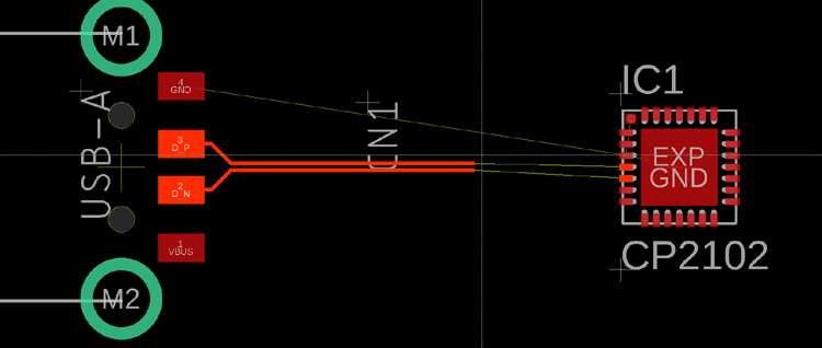
The D+ and D- traces coming from the USB connector are a differential pair. They should be routed parallel to eachother and be as close in length as possible. Minimize the length of the traces and avoid vias on them. More on good routing practices for data traces later (when we get to it in the guide).
Terminating resistors are normally also required on the data lines (commonly two ~22 ohm resistors, one for each line). They are generally placed close to the MCU, but it depends on the chip, refer to documentation.
You can google more information about usb data traces/differential pairs. E.g. This article by Altium.
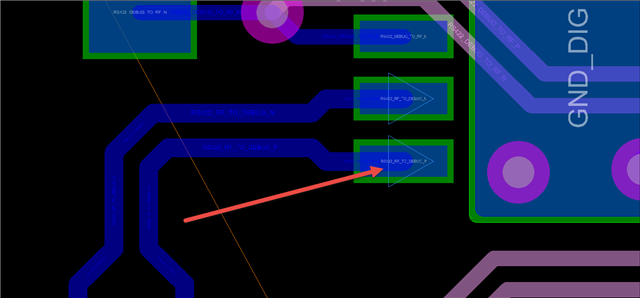
Some examples of differential pair routing.

EEPROM/Flash Storage
This storage is used to store information used by/with programs like VIA/VIAL. E.g. keymap, layout, macros, etc.
Note: Not all MCUs support emulating EEPROM on the chip’s flash. Some chips require an extra component that acts specifically as an external EEPROM. I’ll also discuss this more later.
Bootloader [WIP]
- Flashing headers e.g. AVR-ISP
- SCLK, MOSI, MISO
- SWD header (ARM)
Pinout of an 6 pin AVR ISP header:

Reset Circuit/Switch [WIP]
MCUs generally have a RESET pin that enables debugging functions. E.g. putting the chip into bootloader mode.
Ground fills [WIP]
2 layer keyboard PCBs generally use a ground fill on both the top and bottom layers.
Electrostatic Discharge (ESD) Protection [WIP]
A Complete Guide to ESD Protection
Keyboard PCBs generally have an ESD chip close to the USB connector. This chip just protects the circuit from electrostatic discharge.
Polyfuse/Resettable Fuse [WIP]
A fuse is a component generally found on keyboard PCBs that ensures the entire circuit doesn’t get overwhelmed with current/power. Polyfuses (resettable fuses) are used on keyboard PCBs so that the fuse doesn’t have to be replaced if it trips.
Continue to the next section of the guide [WIP]:
Design Considerations